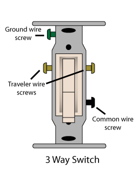


Looking at a set of three way switches standing inside a jobsite environment can be intimidating. But looks can be deceiving, even on paper. Try practicing wiring to help. Electrical Equipment is switched on/off daily using many types of switching devices. Switch wiring should be standard for trained eye. Always use the process of elimination in a safe environment, preferably away from your home since sparks can fly.
Wire nuts for residential use are not intended to contain sparks, only to join two wires. This type of wire termination can also produce sparks while making the termination if voltage is applied.
Before beginning, If you are in the middle of connecting a three-way circuit and you have all the wire pulled, it should not take long. If you are starting from scratch and have nothing installed, please let me know upfront before we get into conversation.
I need to replace a 37 yr old 3-way light switch in the garage. The other switch is in the entry in the house. I purchased a new 3-way switch. When I pulled the old switch out I found 4 wires (2 red, 2 black) and the copper wire. The old switch had the 4 wires pushed in instead of screwed on. The new switch only has 3 screws. I didn’t want to push in the wires, so I attached all the wires except for the extra black wire. When I turned on the power I discovered the extra black wire was hooked to the garage door opener. I went back to Lowe’s to make sure I had the right switch and asked one of the guys what I should do with the extra black wire. He told me I could attach both black wires to one screw. I want to make sure that this is OK or should I just push in the extra black wire and leave the other wires screwed on? I want to make sure I don’t create a fire hazard.
Sounds like you have a 4-way switch installed instead of a 3-way. If you have 4-wires stabbed into 4 separate holes on each corner in the back of that existing switch with a bare ground wrapped around a screw on a 5th screw with the screw-hole factory made to the metal switch frame itself then you had a 4-way switch installed and not a 3-way. You would need to replace it with a 4-way switch. You would then need to attach the 5-wires back exactly as they were attached to the original 4-way switch.
Goal is to make the other lights on the same circuit ( which are all) single poles work. One works the ceiling fan light and one works the ceiling fan motor and one works the closet. Also all the outlets are not powered. I have the single pole switch in the bathroom only (which was goal to reduce from 3 way to single pole). I found 3 black wires capped together deep in the box and found one to power the switch at the expense of the other room lights. Needless to say one son is not happy.
Let me tell you how I interpret your writings and then you can correct me from there,
1.You said you have 3-single pole switches, one for ceiling fan light, one for ceiling fan motor and one for
closet light, correct? These switches have no power going to them, correct? Did you use meter to check if
power was not being supplied to switch, light fixture or both?
This is where I think I only need more info,
2. You went to bathroom looking for hot wire and found one hot wire in that converted 3-way to single-pole
switch, but for some reason that idea did not work out, correct? Where I am lost here? Did you go into this
3-way switch and convert it to single-pole in order to run a hot to the other 3 switches that have no power?
Help me out so that I understand better. Thanks
Do you know which switch box or light fixture the original branch circuit is connected to? Has any wiring been moved? Have you used a multi-meter to identify anything? If you do not know how to operate a multimeter that is fine, I just need to know where to start.
I reversed a three way switch to a single pole switch. I read on line about traveller wires, and the redwires. Inside the box were three black wires pigtailed together. I unwound one of them and put it in the new switch and voila! But then , the other single pole switches that are on the same circuit don’t turn on. No problem during the day, but a problem at night. What to do?
What are you trying to accomplish?
3 way switch on each end of run. 2 half hot outlets with several all hot outlets between. half hot lights lamp, but circuit breaker pops when light is turned off at either switch. Any suggestions?
The switched part of the circuit has a problem. If you have not resolved let me know.
Two ceiling fans on one wall switch & Breaker. Closest ceil fan/light to switch turns on, off, fan works right, all works right. Second Fan/light appears run from first fan’s switch box (unsure about that but suspect it. For this question forget the internal fan/light wiring for 2nd light/fan. With 2nd fan disconnected checking voltage on three wire supply wire (black, white (neutral) and copper (ground) yields the following results. Black wire (Hot) has no connection or voltage appearing on it, no continuity to ground or Neutral. White (Neutral) wire has zero volts (to ground) copper wire & outlet box when wall switch is turned on and 1st fan is working (lights burning, fan running). When wall switch is turned off first fan is turned off (light(s) off & fan off) but 120 VAC appears on the White (neutral) wire coming out of 2nd fans ceiling box. Regardless of switch position black wire (hot) has 0 volts on it. White wire only has 120 V when wall switch is in OFF position but when ON (and it should have 120VAC appearing it has 0 Volts and first fan works as it should. ALL voltages (white neutral wire of 2nd fan when off) and all voltages when wall switch is on disappear and are off when the Breaker box breaker for this circuit is tripped or turned off.
I first thought there was back feeding voltage from another circuit however that voltage on the and fan Neutral (white) wire disappears when the breaker (for the first fan and the wall switch) is tripped. Any ideas what’s going on here? My thought is that the Hot (Black) wire is just disconnected somewhere in the circuit and this is not a two/three way switch. I cannot envision why 120VAC appears on the White (Neutral) wire of the 2nd fan when the wall switch is turned off.
One other piece of information. When the ground was used as a Neutral wire and the white wire connected to the Fan’s Light/fan Hot wires and the wall switch turned on then one of the two fan/lights would iight and the other would be off and when the wall switch was flipped the opposite direction (off) then the fans would alternate being on with the 2nd fan/light on and the first off. I was also told that at one time both fans/lights were on at the same time and worked but just went off one day and never came back on right.
Last info: on the 2nd fan I observed and noticed that whoever hooked/wired up the fan/light did so with the light (HOT) wire pinched between the fans support and the fixture and caused it to short to the fan case & metal holder. There was an obvious burnt spot on the brass where an arc happened at one time due to this pinched wire. Has anyone seen this before and any ideas on troubleshooting as to finding the reason why both fans will not light at the same time, why 120VAC would appear on the Neutral (white) wire of the 2nd fan (farthest away from the wall switch) when the wall switch was in the OFF position breaking power from the breaker box yet all power/voltage is gone when the single branch circuit breaker is thrown?
Thanks in advance
2nd part of question,
In this situation a three wire switch or circuit doesn’t apply. Fan & Light (from fans) are tied together and connected to Black/Hot wire (first fan). I cannot visually see wiring in the box above the 1st fan but going into the 2nd fan’s junction box there is only the one wire with three connectors (bare copper-ground, White (neut) and black (hot)). It is at the 2nd box that nothing is measured on the black (hot) wire as it appears not connected to anything. Also at the 2nd fan box is where the white wire has 120 VAC when the wall switch is in off position and 0 (zero) volts when it is in the on position. Wall Switch in on position applies power to 1st fan running fan & light. There is no 2nd switch and apparently only one 3 conductor wire from awl switch to 1st fan.
Your last reply was spot on, thanks. I think the key is what I didn’t do which is remove the 1st ceiling fan (that is in series with the 2nd) from the circuit and take measurements. The real brain twister (to me) was how when the wall switch was turned OFF that 120VAC appeared on the neutral (white) wire measured to bare copper ground wire (at 2nd ceiling fan). The wall switch only was connected to (broke) one wire which was white also in color and yes I know the switch should break the hot wire but it appears that whoever wired it from the start used the white (neutral) wire as the hot. Even though if that’s the case there shouldn’t be 120 VAC on the white wire of the 2nd fan when the wall switch is turned off.
I’ll let you know if I’m the one that removes the 1st fan and does the checking but I’ve recommended that my son in law (their house) call a licensed electrician, which I’m not. I got my electrical training during Electronic’s study/training in college and although I feel comfortable around electricity sometime something comes up (like this) that blows my mind and I know shouldn’t be. This is the third (things that make you go Umm) moment I have encountered while working around electrical problems. Thanks for all your input and feedback.
I moved your questions to the How to install a 3-way switch category. Go to that category when you reply back. I will post a hand drawn 3-way switch drawing. If it is not clear let me know. Thanks for visiting and please Google plus me on the upper right hand side of my site. That is all I ask and pass the word! Thanks,
https://electricalanswerman.com